使用Platformio平台的libopencm3开发框架来开发STM32G0,下面介绍SD卡模块的使用方法。

1 新建项目

  • 在PIO主页新建项目spi_sdcard,框架选择libopencm3,开发板选择 MonkeyPi_STM32_G070RB;
  • 新建完成后在src目录新建主程序文件main.c;
  • 然后更改项目文件platformio.ini的烧写和调试方式:
1
2
upload_protocol = cmsis-dap
debug_tool = cmsis-dap

2 编写程序

2.1 加入FATFS库
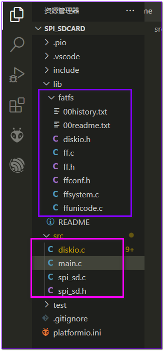
  • 从网站fatfs http://elm-chan.org/fsw/ff/00index_e.html 下载最新的源码;

  • 工程目录lib下新建fatfs文件夹;

  • 然后将fatfs源码的source目录下所有文件放置到工程的lib\fatfs目录下;

  • 将diskio.c文件移动到src目录下,这个文件是需要我们实现的底层接口;

2.2 实现SPI接口的SD读写

在src目录下新建spi_sd.h 和 spi_sd.c 文件,现在目录结构如下:

  • spi_sd.h 头文件
1
2
3
4
5
6
7
8
9
10
11
12
13
14
15
16
17
18
19
20
21
22
23
24
25
26
27
28
29
30
31
32
33
34
35
36
37
38
39
/**
* @file spi_sd.h
* @author MakerInChina (makerinchina.cn)
* @brief
* @version 0.01
* @date 2022-09-18
*
* @copyright Copyright (c) 2022
*
*/

#ifndef _SPI_SD_HEAD_H_
#define _SPI_SD_HEAD_H_

#include <stdint.h>

/**
* @brief init sd card
*
*/
uint8_t spi_sd_init();

/**
* @brief spi read sd
*
* @param buff
* @param sector
*/
uint8_t spi_sd_read(uint8_t *buff, uint32_t sector);

/**
* @brief spi write sd
*
* @param buff
* @param sector
*/
uint8_t spi_sd_write(uint8_t *buff, uint32_t sector);

#endif //!_SPI_SD_HEAD_H_
  • spi_sd.c 实现
1
2
3
4
5
6
7
8
9
10
11
12
13
14
15
16
17
18
19
20
21
22
23
24
25
26
27
28
29
30
31
32
33
34
35
36
37
38
39
40
41
42
43
44
45
46
47
48
49
50
51
52
53
54
55
56
57
58
59
60
61
62
63
64
65
66
67
68
69
70
71
72
73
74
75
76
77
78
79
80
81
82
83
84
85
86
87
88
89
90
91
92
93
94
95
96
97
98
99
100
101
102
103
104
105
106
107
108
109
110
111
112
113
114
115
116
117
118
119
120
121
122
123
124
125
126
127
128
129
130
131
132
133
134
135
136
137
138
139
140
141
142
143
144
145
146
147
148
149
150
151
152
153
154
155
156
157
158
159
160
161
162
163
164
165
166
167
168
169
170
171
172
173
174
175
176
177
178
179
180
181
182
183
184
185
186
187
188
189
190
191
192
193
194
195
196
197
198
199
200
201
202
203
204
205
206
207
208
209
210
211
212
213
214
215
216
217
218
219
220
221
222
223
224
225
226
227
228
229
230
231
232
233
234
235
236
237
238
239
240
241
242
243
244
245
/**
* @file spi_sd.c
* @author MakerInChina (makerinchina.cn)
* @brief
* @version 0.01
* @date 2022-09-18
*
* @copyright Copyright (c) 2022
*
*/

#include "spi_sd.h"

#include <libopencm3/stm32/spi.h>
#include <libopencm3/stm32/gpio.h>

#define SDSPI SPI1
#define SD_CS GPIO4
#define SD_PORT GPIOA

#define spi_cs_deselect() gpio_set(SD_PORT, SD_CS)
#define spi_cs_select() gpio_clear(SD_PORT, SD_CS)


/* Definitions for MMC/SDC command */
#define CMD0 (0x40+0) /* GO_IDLE_STATE */
#define CMD1 (0x40+1) /* SEND_OP_COND (MMC) */
#define ACMD41 (0xC0+41) /* SEND_OP_COND (SDC) */
#define CMD8 (0x40+8) /* SEND_IF_COND */
#define CMD9 (0x40+9) /* SEND_CSD */
#define CMD10 (0x40+10) /* SEND_CID */
#define CMD12 (0x40+12) /* STOP_TRANSMISSION */
#define ACMD13 (0xC0+13) /* SD_STATUS (SDC) */
#define CMD16 (0x40+16) /* SET_BLOCKLEN */
#define CMD17 (0x40+17) /* READ_SINGLE_BLOCK */
#define CMD18 (0x40+18) /* READ_MULTIPLE_BLOCK */
#define CMD23 (0x40+23) /* SET_BLOCK_COUNT (MMC) */
#define ACMD23 (0xC0+23) /* SET_WR_BLK_ERASE_COUNT (SDC) */
#define CMD24 (0x40+24) /* WRITE_BLOCK */
#define CMD25 (0x40+25) /* WRITE_MULTIPLE_BLOCK */
#define CMD55 (0x40+55) /* APP_CMD */
#define CMD58 (0x40+58) /* READ_OCR */

#define CT_MMC 0x01 /* MMC ver 3 */
#define CT_SD1 0x02 /* SD ver 1 */
#define CT_SD2 0x04 /* SD ver 2 */
#define CT_SDC (CT_SD1|CT_SD2) /* SD */
#define CT_BLOCK 0x08 /* Block addressing */

static uint8_t spi_read_write8(uint32_t spi, uint8_t tx);
static uint8_t wait_ready(void);
static uint8_t send_cmd (uint8_t cmd,uint32_t arg);
static void set_spi_slow();
static void set_spi_fast();

/**
* @brief init sd card
*
*/
uint8_t spi_sd_init()
{
uint8_t n, cmd, ty, ocr[4];
uint16_t i;


//init with low speed
// set_spi_slow();

spi_cs_select();

for (n = 10; n; n--) spi_read_write8(SDSPI,0xff); /* 80 dummy clocks */

ty = 0;

/* Enter Idle state */
ty = send_cmd(CMD0, 0);

// printf(" > enter idle:%d\n", ty);

/* Initialization timeout of 1000 milliseconds */
/* SDHC */

if(ty == 1){

if (send_cmd(CMD8, 0x1AA) == 1){ /* SDv2? */
/* Get trailing return value of R7 response */
for (n = 0; n < 4; n++) ocr[n] = spi_read_write8(SDSPI,0xff);
/* The card can work at VDD range of 2.7-3.6V */
if (ocr[2] == 0x01 && ocr[3] == 0xAA){
/* Wait for leaving idle state (ACMD41 with HCS bit) */
i=0xfff;
while (--i && send_cmd(ACMD41, 1UL << 30));
if (i && send_cmd(CMD58, 0) == 0){
/* Check CCS bit in the OCR */
for (n = 0; n < 4; n++) ocr[n] = spi_read_write8(SDSPI,0xff);
ty = (ocr[0] & 0x40) ? CT_SD2 | CT_BLOCK : CT_SD2;

}
}
} else { /* Not SDv2 card */
// if (send_cmd(ACMD41, 0) <= 1) { /* SDv1 or MMC? */
// ty = CT_SD1; cmd = ACMD41; /* SDv1 (ACMD41(0)) */
// } else {
// ty = CT_MMC; cmd = CMD1; /* MMCv3 (CMD1(0)) */
// }

// while (SPI_Timer_Status() && send_cmd(cmd, 0)) ; /* Wait for end of initialization */
// if (!SPI_Timer_Status() || send_cmd(CMD16, 512) != 0) /* Set block length: 512 */
// ty = 0;
}

}
//CardType = ty;


spi_cs_deselect();
spi_read_write8(SDSPI,0xff);
while (SPI_SR(SDSPI) & SPI_SR_BSY);

set_spi_fast();

return ty;
}

/**
* @brief spi read sd
*
* @param buff
* @param sector
*/
uint8_t spi_sd_read(uint8_t *buff, uint32_t sector)
{
uint8_t result;
uint16_t cnt=0xffff;
spi_cs_select();
result=send_cmd(CMD17, sector); //CMD17 даташит стр 50 и 96
if (result){spi_cs_deselect(); return 5;} //Выйти, если результат не 0x00

spi_read_write8(SDSPI,0xff);
cnt=0;
do result=spi_read_write8(SDSPI,0xff); while ((result!=0xFE)&&--cnt);
if(!cnt){spi_cs_deselect(); return 5;}

for (cnt=0;cnt<512;cnt++) *buff++=spi_read_write8(SDSPI,0xff);

spi_read_write8(SDSPI,0xff);
spi_cs_deselect();
spi_read_write8(SDSPI,0xff);

return 0;
}

/**
* @brief spi write sd
*
* @param buff
* @param sector
*/
uint8_t spi_sd_write(uint8_t *buff, uint32_t sector)
{
uint8_t result;
uint16_t cnt=0xffff;
spi_cs_select();
result=send_cmd(CMD24,sector); //CMD24
if(result){spi_cs_deselect(); return 6;} //
spi_read_write8(SDSPI,0xff);
spi_read_write8(SDSPI,0xfe);//
for (cnt=0;cnt<512;cnt++) spi_read_write8(SDSPI,buff[cnt]); //Данные
spi_read_write8(SDSPI,0xff);
result=spi_read_write8(SDSPI,0xff);
//result=wait_ready();
if((result&0x05)!=0x05){spi_cs_deselect(); return 6;}
//spi_read_write8(SDSPI,0xff);
while (SPI_SR(SDSPI) & SPI_SR_BSY);
//
spi_cs_deselect();
spi_read_write8(SDSPI,0xff);
return 0;
}


static void set_spi_slow()
{
// spi_disable(SDSPI);
spi_set_baudrate_prescaler(SDSPI,SPI_CR1_BAUDRATE_FPCLK_DIV_128);
// spi_enable(SDSPI);
}

static void set_spi_fast()
{
// spi_disable(SDSPI);
spi_set_baudrate_prescaler(SDSPI,SPI_CR1_BAUDRATE_FPCLK_DIV_8);
// spi_enable(SDSPI);
}

static uint8_t spi_read_write8(uint32_t spi, uint8_t tx)
{
spi_send8(spi, tx);
return spi_read8(spi);
}

static uint8_t wait_ready(void)
{
uint8_t res;
uint16_t cnt=0xffff;
spi_read_write8(SDSPI, 0xff);
do res = spi_read_write8(SDSPI, 0xff); while ((res!=0xFF)&& --cnt );
return res;
}

static uint8_t send_cmd (uint8_t cmd,uint32_t arg)
{
uint8_t n, res;

/* ACMD<n> is the command sequence of CMD55-CMD<n> */
if (cmd & 0x80){
cmd &= 0x7F;
res = send_cmd(CMD55, 0);
if (res > 1) return res;
}

if (wait_ready()!=0xFF) return 0xFF;
/* Send command packet */
spi_read_write8(SDSPI, cmd); /* Start + Command index */
spi_read_write8(SDSPI,(uint8_t)(arg >> 24)); /* Argument[31..24] */
spi_read_write8(SDSPI,(uint8_t)(arg >> 16)); /* Argument[23..16] */
spi_read_write8(SDSPI,(uint8_t)(arg >> 8)); /* Argument[15..8] */
spi_read_write8(SDSPI,(uint8_t)arg); /* Argument[7..0] */
n = 0x01; /* Dummy CRC + Stop */
if (cmd == CMD0) n = 0x95; /* Valid CRC for CMD0(0) */
if (cmd == CMD8) n = 0x87; /* Valid CRC for CMD8(0x1AA) */
spi_read_write8(SDSPI,n);
/* Receive command response */
if (cmd == CMD12) spi_read_write8(SDSPI,0xff);
/* Skip a stuff byte when stop reading */
/* Wait for a valid response in timeout of 10 attempts */
n = 10;
do res=spi_read_write8(SDSPI,0xff); while ((res & 0x80) && --n);

while (SPI_SR(SDSPI) & SPI_SR_BSY); //wait if busy

return res; /* Return with the response value */
}

注:这里初始化部分只写了SDv2的判断;

  • diskio.c 调用 spi_sd的读写接口:
1
2
3
4
5
6
7
8
9
10
11
12
13
14
15
16
17
18
19
20
21
22
23
24
25
26
27
28
29
30
31
32
33
34
35
36
37
38
39
40
41
42
43
/*-----------------------------------------------------------------------*/
/* Read Sector(s) */
/*-----------------------------------------------------------------------*/

DRESULT disk_read (
BYTE pdrv, /* Physical drive nmuber to identify the drive */
BYTE *buff, /* Data buffer to store read data */
LBA_t sector, /* Start sector in LBA */
UINT count /* Number of sectors to read */
)
{
while(count){
if (spi_sd_read(buff,sector)) return RES_ERROR;
--count;
++sector;
buff+=512;
}
return RES_OK;
}


/*-----------------------------------------------------------------------*/
/* Write Sector(s) */
/*-----------------------------------------------------------------------*/

#if FF_FS_READONLY == 0

DRESULT disk_write (
BYTE pdrv, /* Physical drive nmuber to identify the drive */
const BYTE *buff, /* Data to be written */
LBA_t sector, /* Start sector in LBA */
UINT count /* Number of sectors to write */
)
{
while(count){
if(spi_sd_write(buff,sector)) return RES_ERROR;
--count;
++sector;
buff+=512;
}
return RES_OK;
}
2.3 SPI接口配置
1
2
3
4
5
6
7
8
9
10
11
12
13
14
15
16
17
18
19
20
21
22
23
24
25
26
27
28
29
30
31
32
33
34
35
36
37
38
39
40
41
42
43
44
45
46
47
48
49
50
51
52
53
54
55
56
57
58
59
60
61
62
63
64
65
66
static void spi1_init(void){
//spi1 - display
/* Enable SPI1 Periph and gpio clocks */
rcc_periph_clock_enable(RCC_SPI1);
rcc_periph_clock_enable(RCC_GPIOA);

/* Configure GPIOs:
*
* SCK=PA5
* MOSI=PA7
* MISO=PA6
*
* for SD card
* SDCS PA4
*/

//MOSI & SCK & MISO
gpio_mode_setup(GPIOA, GPIO_MODE_AF, GPIO_PUPD_NONE,GPIO5|GPIO7|GPIO6);
gpio_set_af(GPIOA,GPIO_AF0,GPIO5|GPIO7|GPIO6);
gpio_set_output_options(GPIOA, GPIO_OTYPE_PP,GPIO_OSPEED_LOW,GPIO5|GPIO7|GPIO6);

//SDCS
gpio_mode_setup(GPIOA,GPIO_MODE_OUTPUT,GPIO_PUPD_NONE,GPIO4);

gpio_set(GPIOA,GPIO4);

/* Reset SPI, SPI_CR1 register cleared, SPI is disabled */
spi_reset(SPI1);

/* Set up SPI in Master mode with:
* Clock baud rate
* Clock polarity
* Clock phase
* Frame format MSB
*/
spi_init_master(SPI1, SPI_CR1_BAUDRATE_FPCLK_DIV_128,
SPI_CR1_CPOL_CLK_TO_0_WHEN_IDLE,
SPI_CR1_CPHA_CLK_TRANSITION_1,
SPI_CR1_MSBFIRST);

spi_set_data_size(SPI1,SPI_CR2_DS_8BIT);
spi_set_full_duplex_mode(SPI1);

spi_fifo_reception_threshold_8bit(SPI1);

SPI_CR2(SPI1) |= SPI_CR2_NSSP; //NSSP, ?? clock continus
// spi_set_unidirectional_mode(SPI1);
// SPI_CR2(SPI1) &= (~SPI_CR2_FRF_TI_MODE); //motorala mode
// SPI_CR2(SPI1) |= SPI_CR2_FRF_TI_MODE;

/*
* Set NSS management to software.
*
* Note:
* Setting nss high is very important, even if we are controlling
* the GPIO
* ourselves this bit needs to be at least set to 1, otherwise the spi
* peripheral will not send any data out.
*/
spi_enable_software_slave_management(SPI1);
spi_set_nss_high(SPI1);

/* Enable SPI1 periph. */
spi_enable(SPI1);

}

SPI使用的SPI1,CS使用软件控制;

2.4 SD卡读写测试
1
2
3
4
5
6
7
8
9
10
11
12
13
14
15
16
17
18
19
20
21
22
23
24
25
26
27
28
29
30
31
32
33
34
35
36
37
38
39
40
41
42
43
44
45
46
47
48
49
50
51
52
53
printf(" init spi.\n");

//spi
spi1_init();

//sd
uint8_t sd_type = spi_sd_init();

//sdv2: 0x08|0x04 . 0x0c
// printf(" sd_type: %x\n", sd_type);

FATFS fs;
FRESULT res;
res = f_mount(&fs, "", 0);
if(res != FR_OK) {
printf("mount fs failed, res = %d\r\n", res);
return -1;
}else{
printf(" mount fs OK.\n");
}

FIL fd;

res = f_open(&fd, "test.txt", FA_CREATE_ALWAYS|FA_WRITE);
if(res != FR_OK){
printf("open file failed: %d\n", res);
}else{
printf("open file OK.\n");
}

char *buff = "test data to write to fs\n";
uint32_t len = 0;
res = f_write(&fd,buff, strlen(buff),&len);
if(res != FR_OK){
printf(" write file failed.\n");
}else{
printf(" write file OK, write size %d .\n", len);
}

res = f_close(&fd);
if(res != FR_OK){
printf(" close fs failed.\n");
}else{
printf(" close fs OK.\n");
}

res = f_unmount("");
if(res != FR_OK) {
printf("Unmount fs failed, res = %d\r\n", res);
return -1;
}else{
printf("Unmound fs OK.\n");
}

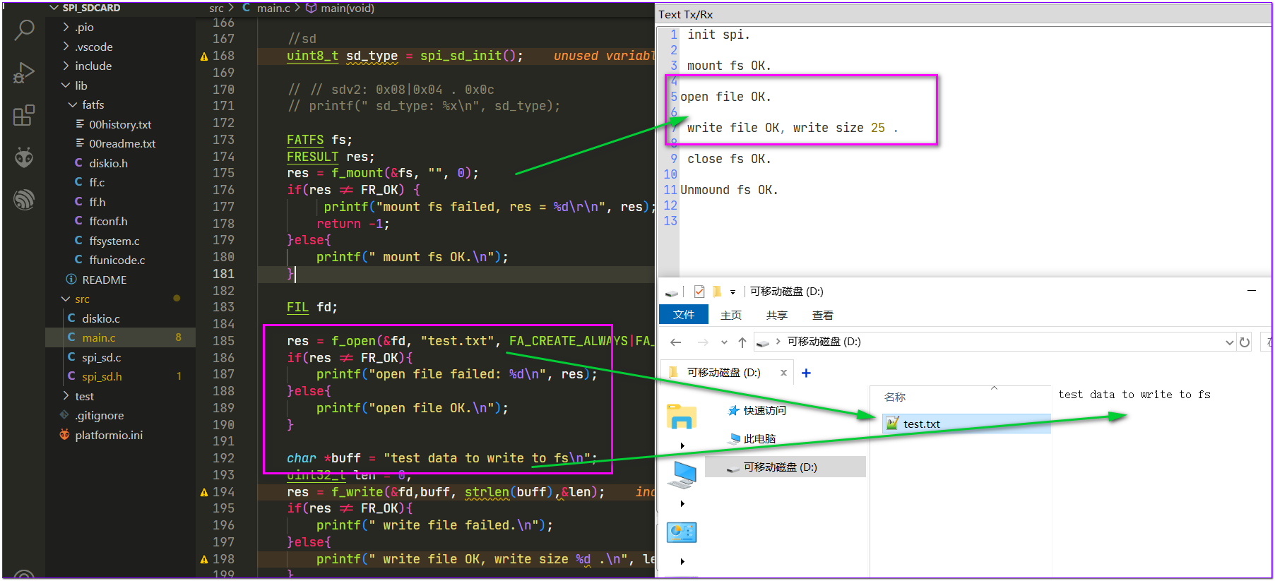
main中测试SD卡挂载、读写;

3 硬件连接

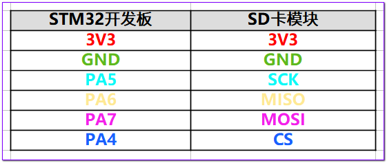
硬件引脚按如下方式连接到SPI1:

4 烧写测试

将程序烧写到开发板后,打开串口,可以看到测试成功,卡中写入文件在电脑显示正确: